Extension Factory Builder

Wednesday, February 15, 2012

TECHNIQUES TO RESTORE ORIGINAL STRENGTH OF STRUCTURES

The techniques are described below among with other restoration measures. Small cracks


If the cracks are reasonably small (opening width=0.075mm), the technique to restore the original tensile strength of the cracked element is by pressure injection of epoxy. The procedure is as follows.

The external surfaces are cleaned of non-structural materials and plastic ports are placed among the surface of the cracks on both sides of the member and are secured in place with an epoxy sealant. The centre to centre spacing of these ports may be approximately equal to the thickness of the element. After the sealant has cured, a low viscosity epoxy resin is injected into one port at a time, beginning at the lowest part of the crack in case it is vertical or at one end of the crack in case it is horizontal.
The resin is injected till it is seen flowing from the opposite sides of the member at the corresponding port or from the next higher port on the same side of the member. The injection port should be closed at this stage and injection equipment moved to next port and so on.
The small the crack, the higher is the pressure or more closely spaced should be the ports so as to obtain the complete penetration of the epoxy material throughout the depth and width of member. Larger cracks will permit larger port spacing, depending upon width of the member. This technique is appropriate for all types of structural elements- beams, columns, walls and floor units in masonry as well as concrete structures. Two items should however be taken care of in such type of repair:
In the case of loss of bond between reinforcement bar and concrete, if the concrete, if the concrete adjacent to the bar has been pulverised to a very fine powder, this powder will dam the epoxy from saturating the region. So it should be cleaned properly by air or water pressure prior to injection of epoxy.It has been stated that cracks smaller than 0.75mm may be difficult pressure inject. So cracks smaller than this should not be repaired by this method.Large cracks and crushed concrete


For cracks wider than about 6mm or for regions in which the concrete or masonry has crushed, a treatment other than injection is indicated. The following procedure may be adopted:
The loose material is removed and replaced with expansive cement mortar, quick setting cement or gypsum cement mortar.Where found necessary, additional shear of flexural reinforcement is provided in the region of repairs. This reinforcement could be covered by mortar to give further strength as well as protection to the reinforcement.In areas of very severe damage, replacement of the member or portion of member can be carried out. In case of damage to walls and floor diaphragms, steel mesh could be provided on the outside of the surface and nailed or bolted to the wall. Then it may be covered or plastered or micro-concrete.Fractured, excessively yielded and buckled reinforcement


In the case of severely damaged reinforced concrete member, it is possible that the reinforcement would have buckled, or elongated or excessively yielding may have occurred. This element can be repaired by replacing the old portion of steel with new steel using butt welding or lap welding.
Splicing by overlapping will be risky. If repair has to be made without removal of the existing steel, the best approach would depend upon the space available in the original member. Additional stirrup ties are to be added in the damaged portion before concreting so as to confine the concrete and enclose the longitudinal bars to prevent their buckling in future.
In some cases it may be necessary to anchor additional steel into existing concrete. A common technique for providing the anchorage uses the following procedure:
A hole larger than the bar is drilled. The hole is filled with epoxy, expanding cement, or other strength grouting material. The bar is pushed into the place and held there until the grout has set.


Fractured wooden members and joints
Since wood is an easily workable material, it will be easy to restore the strength of wooden members, beams, columns, struts and ties by splicing additional material. The weathered or rotten wood should first be removed. Nails, wood screws or steel bolts will be most convenient as connectors. It will be advisable to use straps to cover all such splices and joints so as to keep them tight and stiff.

Sunday, February 12, 2012

GATE 2012 CIVIL ENGINEERING KEY

GATE 2012 KEY


>>>> DOWNLOAD <<<<

Thursday, January 19, 2012

Tougher, lighter wind turbine blade developed: Polyurethane reinforced with carbon nanotubes


Efforts to build larger wind turbines able to capture more energy from the air are stymied by the weight of blades. A Case Western Reserve University researcher has built a prototype blade that is substantially lighter and eight times tougher and more durable than currently used blade materials.


Marcio Loos, a post-doctoral researcher in the Department of Macromolecular Science and Engineering, works with colleagues at Case Western Reserve, and investigators from Bayer MaterialScience in Pittsburgh, and Molded Fiber Glass Co. in Ashtabula, Ohio, comparing the properties of new materials with the current standards used in blade manufacturing.

On his own, Loos went to the lab on weekends and built the world's first polyurethane blade reinforced with carbon nanotubes. He wanted to be sure the composite that was scoring best on preliminary tests could be molded into the right shape and maintain properties.

Using a small commercial blade as a template, he manufactured a 29-inch blade that is substantially lighter, more rigid and tougher.

"The idea behind all this is the need to develop stronger and lighter materials which will enable manufacturing of blades for larger rotors," Loos said.

That's an industry goal.

In order to achieve the expansion expected in the market for wind energy, turbines need a bigger share of the wind. But, simply building larger blades isn't a smart answer.

The heavier the blades, the more wind is needed to turn the rotor. That means less energy is captured. And the more the blades flex in the wind, the more they lose the optimal shape for catching moving air, so, even less energy is captured.

Lighter, stiffer blades enable maximum energy and production.

"Results of mechanical testing for the carbon nanotube reinforced polyurethane show that this material outperforms the currently used resins for wind blades applications," said Ica Manas-Zloczower, professor of macromolecular science and engineering and associate dean in the Case School of Engineering.

Loos is working in the Manas-Zloczower lab where she and Chemical Engineering Professor Donald L. Feke, a vice provost at the university, serve as advisors on the project.

In a comparison of reinforcing materials, the researchers found carbon nanotubes are lighter per unit of volume than carbon fiber and aluminum and had more than 5 times the tensile strength of carbon fiber and more than 60 times that of aluminum.

Fatigue testing showed the reinforced polyurethane composite lasts about eight times longer than epoxy reinforced with fiberglass. The new material was also about eight times tougher in delamination fracture tests.

The performance in each test was even better when compared to vinyl ester reinforced with fiberglass, another material used to make blades.

The new composite also has shown fracture growth rates at a fraction of the rates found for traditional epoxy and vinyl ester composites.

Loos and the rest of the team are continuing to test for the optimal conditions for the stable dispersion of nanotubes, the best distribution within the polyurethane and methods to make that happen.

The functional prototype blades built by Loos, which were used to turn a 400-watt turbine, will be stored in our laboratory, Manas-Zloczower said. "They will be used to emphasize the significant potential of carbon nanotube reinforced polyurethane systems for use in the next generation of wind turbine blades."


Disclaimer: Views expressed in this article do not necessarily reflect those of Royal Civilizers or its staff.

Shoring, Underpinning and Scaffolding


             Shoring is a general term used in construction to describe the process of supporting a structure in order to prevent collapse so that construction can proceed. The phrase can also be used as a noun to refer to the materials used in the process. Underpinning is the process of strengthening and stabilizing the foundation of an existing building or other structure.


Scaffolding is a temporary frame used to support people and material in the construction or repair of buildings and other large structures.


Shoring is used to support the beams and floors in a building while a column or wall is removed. In this situation vertical supports are used as a temporary replacement for the building columns or walls.

Trenches – During excavation, shoring systems provide safety for workers in a trench and speed excavation. In this case, shoring should not be confused with shielding. Shoring is designed to prevent collapse where shielding is only designed to protect workers when collapses occur. concrete structures shoring, in this case also referred to as falsework, provides temporary support until the concrete becomes hard and achieves the desired strength to support loads.

Shoring Techniques

Raking Shore :
Raking Shores consist of one or more timbers sloping between the face of the structure to be supported and the ground. The most effective support is given if the raker meets the wall at an angle of 60 to 70 degrees. A wall-plate is typically used to increase the area of support.

Hydraulic Shoring :
Hydraulic shoring is the use of hydraulic pistons that can be pumped outward until they press up against the trench walls. They are typically combined with steel plate or plywood, either being 1-1/8? thick plywood, or special heavy Finland Form (FINFORM) 7/8? thick.

Beam and Plate :
Beam and Plate steel I-beams are driven into the ground and steel plates are slid in amongst them. A similar method that uses wood planks is called soldier boarding. Hydraulics tend to be faster and easier; the other methods tend to be used for longer term applications or larger excavations.

Soil Nailing :
Soil nailing is a technique in which soil slopes, excavations or retaining walls are reinforced by the insertion of relatively slender elements – normally steel reinforcing bars. The bars are usually installed into a pre-drilled hole and then grouted into place or drilled and grouted simultaneously. They are usually installed untensioned at a slight downward inclination. A rigid or flexible facing (often sprayed concrete) or isolated soil nail heads may be used at the surface.

Continuous Flight Augering :
Continuous Flight Augering (CFA) is a method used to create concrete piles to support soil so that excavation can take place nearby. A Continuous Flight Augering drill is used to excavate a hole and concrete is injected through a hollow shaft under pressure as the auger is extracted. This creates a continuous pile without ever leaving an open hole.

Underpinning :
Underpinning may be necessary for a variety of reasons:
* The original foundation is simply not strong or stable enough, e.g. due to decay of wooden piles under the foundation.
* The usage of the structure has changed.
* The properties of the soil supporting the foundation may have changed (possibly through subsidence) or were mischaracterized during planning.
* The construction of nearby structures necessitates the excavation of soil supporting existing foundations.
* It is more economical, due to land price or otherwise, to work on the present structure’s foundation than to build a new one.
Underpinning is accomplished by extending the foundation in depth or in breadth so it either rests on a stronger soil stratum or distributes its load across a greater area. Use of micropiles and jet grouting are common methods in underpinning. An alternative to underpinning is the strengthening of the soil by the introduction of a grout. All of these processes are generally expensive and elaborate.

Monday, October 31, 2011

Civil Engineering FORMULAS by Tyler G.Hicks.

The best collection of Civil Engineering Formulas by Tyler G.Hicks.


Download Links:

Wednesday, October 26, 2011

VELOCITY DISTRIBUTION IN OPEN CHANNEL

The measured velocity in an open channel will always vary across the channel section because of friction along the boundary. Neither is this velocity distribution usually axisymmetric (as it is in pipe flow) due to the existence of the free surface. It might be expected to find the maximum velocity at the free surface where the shear force is zero but this is not the case. The maximum velocity is usually found just below the surface. The explanation for this is the presence of secondary currents which are circulating from the boundaries towards the section centre and resistance at the air/water interface. These have been found in both laboratory measurements and 3d numerical simulation of turbulence.
The figure below shows some typical velocity distributions across some channel cross sections. The number indicates percentage of maximum velocity.

                                                           Figure of velocity distributions 


To determine the values of ? and ? the velocity distribution must have been measured (or be known in some way). In irregular channels where the flow may be divided into distinct regions ? may exceed 2 and should be included in the Bernoulli equation.
The figure below is a typical example of this situation. The channel may be of this shape when a river is in flood – this is known as a compound channel.

Figure of a compound channel with three regions of flow
If the channel is divided as shown into three regions and making the assumption that ? = 1 for each then


Where


Saturday, October 15, 2011

How to open MS Office 2007 file in Ms Office 2003

Hello World!!

Well you may experience with a problem of opening Ms Office 2007 files [.docx, .xlsx,etc] in Ms Office 2003. This happens due to the compatibility difference between these two versions. It is obvious that difference is must between old and new versions. We can fix all these errors by adding the compatibility pack to the Ms Office 2003 which helps to run in low RAM too.


Download this Compatibility Pack from below servers:


4-1 Civil Engineering Previous Question Papers free download

EXAMS TIME ??


B.tech IV-I semester previous question papers May 2011 are here to download:


Monday, September 26, 2011

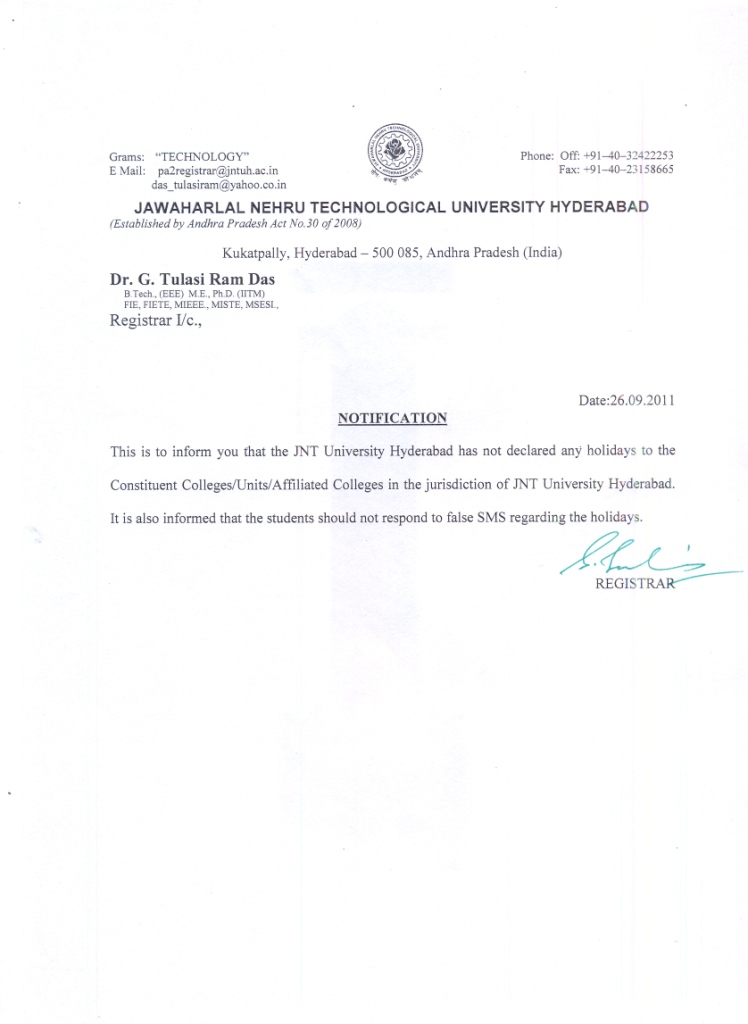
No holidays as per JNTUH due to Telangana Bandh in A.P

Circular to Constituent Colleges / Units / Affiliated Colleges:

No holidays are declared to any JNTUH affiliated colleges as per JNTU notification.


Saturday, September 17, 2011

ONLINE APPLICATION FOR GATE 2012

GATE 2012

This time the total application procedure of GATE is changed. Everyone  should apply in online. Everything is un-editable after once you have submitted your details. So, please fill your details carefully. Read all instructions and FAQ page for clear procedure of application.
The new RULE passed in 2012 that pre-final [3rd year] year students are not eligible to apply GATE 2012.


CLICK IMAGE TO READ THE FAQ PAGE


CLICK IMAGE TO APPLY ONLINE


Wednesday, August 31, 2011

Anna Hazare Jan lokpal bill – Theme song

The Jan Lokpal Bill (Hindi: जन लोकपाल विधेयक), also referred to as the Citizen’s Ombudsman Bill, is a proposed anti-corruption law in India. It was proposed by prominent civil society activists as a more effective improvement to the original Lokpal bill, which is currently being proposed by the the Government of India. The prefix Jan was added to signify the fact that these improvements include input provided by “ordinary citizens” through an activist-driven, non-governmental public consultation.

Drafted by Justice Santosh Hegde (former Supreme Court Judge and former Lokayukta of Karnataka), Prashant Bhushan (Supreme Court Lawyer) and Arvind Kejriwal (RTI activist), the draft Bill to regard a system where a corrupted  person found guilty would go to jail within two years of the complaint being made and his ill-gotten wealth being impounded. It also seeks power to the Jan Lokpal Bill to prosecute all politicians and bureaucrats without government permission and intimation.


Wednesday, August 17, 2011

Non-destructive methods for testing Concrete

The standard method of evaluating the quality of concrete in buildings or structures is to test specimens cast simultaneously for compressive, flexural and tensile strengths. The main disadvantages are that results are not obtained immediately; that concrete in specimens may differ from that in the actual structure as a result of different curing and compaction conditions; and that strength properties of a concrete specimen depend on its size and shape.

Although there can be no direct measurement of the strength properties of structural concrete for the simple reason that strength determination involves destructive stresses, several non- destructive methods of assessment have been developed. These depend on the fact that certain physical properties of concrete can be related to strength and can be measured by non-destructive methods. Such properties include hardness, resistance to penetration by projectiles, rebound capacity and ability to transmit ultrasonic pulses and X- and Y-rays. These non-destructive methods may be categorized as penetration tests, rebound tests, pull-out techniques, dynamic tests, radioactive tests, maturity concept. It is the purpose of this Digest to describe these methods briefly, outlining their advantages and disadvantages.


 Penetration Tests
The Windsor probe is generally considered to be the best means of testing penetration. Equipment consists of a powder-actuated gun or driver, hardened alloy probes, loaded cartridges, a depth gauge for measuring penetration of probes and other related equipment. A probe, diameter 0.25 in. (6.5 mm) and length 3.125 in. (8.0 cm), is driven into the concrete by means of a precision powder charge. Depth of penetration provides an indication of the compressive strength of the concrete. Although calibration charts are provided by the manufacturer, the instrument should be calibrated for type of concrete and type and size of aggregate used.
Limitations and Advantages. The probe test produces quite variable results and should not be expected to give accurate values of concrete strength. It has, however, the potential for providing a quick means of checking quality and maturity of in situ concrete. It also provides a means of assessing strength development with curing. The test is essentially non-destructive, since concrete and structural members can be tested in situ, with only minor patching of holes on exposed faces.

Rebound Tests

The rebound hammer is a surface hardness tester for which an empirical correlation has been established between strength and rebound number. The only known instrument to make use of the rebound principle for concrete testing is the Schmidt hammer, which weighs about 4 lb (1.8 kg) and is suitable for both laboratory and field work. It consists of a spring-controlled hammer mass that slides on a plunger within a tubular housing. The hammer is forced against the surface of the concrete by the spring and the distance of rebound is measured on a scale. The test surface can be horizontal, vertical or at any angle but the instrument must be calibrated in this position.
Calibration can be done with cylinders (6 by 12 in., 15 by 30 cm) of the same cement and aggregate as will be used on the job. The cylinders are capped and firmly held in a compression machine. Several readings are taken, well distributed and reproducible, the average representing the rebound number for the cylinder. This procedure is repeated with several cylinders, after which compressive strengths are obtained.

Limitations and Advantages. The Schmidt hammer provides an inexpensive, simple and quick method of obtaining an indication of concrete strength, but accuracy of ±15 to ±20 per cent is possible only for specimens cast cured and tested under conditions for which calibration curves have been established. The results are affected by factors such as smoothness of surface, size and shape of specimen, moisture condition of the concrete, type of cement and coarse aggregate, and extent of carbonation of surface.

Pull-Out Tests

A pull-out test measures, with a special ram, the force required to pull from the concrete a specially shaped steel rod whose enlarged end has been cast into the concrete to a depth of 3 in. (7.6 cm). The concrete is simultaneously in tension and in shear, but the force required to pull the concrete out can be related to its compressive strength. The pull-out technique can thus measure quantitatively the in-situ strength of concrete when proper correlations have been made. It has been found, over a wide range of strengths, that pull-out strengths have a coefficient of variation comparable to that of compressive strength.
Limitations and Advantages. Although pullout tests do not measure the interior strength of mass concrete, they do give information on the maturity and development of strength of a representative part of it. Such tests have the advantage of measuring quantitatively the strength of concrete in place. Their main disadvantage is that they have to be planned in advance and pull-out assemblies set into the formwork before the concrete is placed. The pull-out, of course, creates some minor damage. The test can be non-destructive, however, if a minimum pull-out force is applied that stops short of failure but makes certain that a minimum strength has been reached. This is information of distinct value in determining when forms can be removed safely.

Dynamic Tests

At present the ultrasonic pulse velocity method is the only one of this type that shows potential for testing concrete strength in situ. It measures the time of travel of an ultrasonic pulse passing through the concrete. The fundamental design features of all commercially available units are very similar, consisting of a pulse generator and a pulse receiver. Pulses are generated by shock-exciting piezo-electric crystals, with similar crystals used in the receiver. The time taken for the pulse to pass through the concrete is measured by electronic measuring circuits.
Pulse velocity tests can be carried out on both laboratory-sized specimens and completed concrete structures, but some factors affect measurement:
  1. There must be smooth contact with the surface under test; a coupling medium such as a thin film of oil is mandatory.
  2. It is desirable for path-lengths to be at least 12 in. (30 cm) in order to avoid any errors introduced by heterogeneity.
  3. It must be recognized that there is an increase in pulse velocity at below-freezing temperature owing to freezing of water; from 5 to 30°C (41 – 86°F) pulse velocities are not temperature dependent.
  4. The presence of reinforcing steel in concrete has an appreciable effect on pulse velocity. It is therefore desirable and often mandatory to choose pulse paths that avoid the influence of reinforcing steel or to make corrections if steel is in the pulse path.
Applications and Limitations: The pulse velocity method is an ideal tool for establishing whether concrete is uniform. It can be used on both existing structures and those under construction. Usually, if large differences in pulse velocity are found within a structure for no apparent reason, there is strong reason to presume that defective or deteriorated concrete is present.
High pulse velocity readings are generally indicative of good quality concrete. A general relation between concrete quality and pulse velocity is given in Table.


General Conditions                Pulse Velocity ft/sec 


 Excellent                                   Above 15,000 


 Good                                          12,000-15,000 


 Questionable                            10,000-12,000 
  

 Poor                                            7,000-10,000 


Very Poor                                    below 7,000 


Fairly good correlation can be obtained between cube compressive strength and pulse velocity. These relations enable the strength of structural concrete to be predicted within ±20 per cent, provided the types of aggregate and mix proportions are constant.

The pulse velocity method has been used to study the effects on concrete of freeze-thaw action, sulphate attack, and acidic waters. Generally, the degree of damage is related to a reduction in pulse velocity. Cracks can also be detected. Great care should be exercised, however, in using pulse velocity measurements for these purposes since it is often difficult to interpret results. Sometimes the pulse does not travel through the damaged portion of the concrete.

The pulse velocity method can also be used to estimate the rate of hardening and strength development of concrete in the early stages to determine when to remove formwork. Holes have to be cut in the formwork so that transducers can be in direct contact with the concrete surface. As concrete ages, the rate of increase of pulse velocity slows down much more rapidly than the rate of development of strength, so that beyond a strength of 2,000 to 3,000 psi (13.6 to 20.4 MPa) accuracy in determining strength is less than ±20%. Accuracy depends on careful calibration and use of the same concrete mix proportions and aggregate in the test samples used for calibration as in the structure.
In summary, ultrasonic pulse velocity tests have a great potential for concrete control, particularly for establishing uniformity and detecting cracks or defects. Its use for predicting strength is much more limited, owing to the large number of variables affecting the relation between strength and pulse velocity.

Radioactive Methods

Radioactive methods of testing concrete can be used to detect the location of reinforcement, measure density and perhaps establish whether honeycombing has occurred in structural concrete units. Gamma radiography is increasingly accepted in England and Europe. The equipment is quite simple and running costs are small, although the initial price can be high. Concrete up to 18 in. (45 cm) thick can be examined without difficulty.

Saturday, August 13, 2011

Averting Bridge Disasters: New Technology Could Save Hundreds of Lives


  • Millions of U.S. drivers cross faulty or obsolete bridges every day, highway statistics show, but it's too costly to fix all these spans or adequately monitor their safety, says a University of Maryland researcher who's developed a new, affordable early warning system.


                    This wireless technology could avert the kind of bridge collapse that killed 13 and injured 145 along Minneapolis' I-35W on Aug. 1, 2007.

"Potentially hundreds of lives could be saved," says University of Maryland electrical engineering researcher Mehdi Kalantari. "One of every four U.S. highway bridges has known structural problems or exceeded its intended life-span. Most only get inspected once every one or two years. That's a bad mix." Kalantari has created tiny wireless sensors that monitor and transmit minute-by-minute data on a bridge's structural integrity. A central computer analyzes the data and instantly warns officials of possible trouble. He plans to scale-up manufacture in the fall.


"If this kind of technology had been available in Minnesota four years ago, there's a good chance the fatal bridge collapse could have been avoided," Kalantari adds. "This new approach makes preventive maintenance affordable -- even at a time when budgets are tight. Officials will be able to catch problems early and will have weeks or month to fix a problem."
More than one-in-four U.S. bridges are either structurally deficient or functionally obsolete, according to a 2009 estimate by the U.S. Society of Civil Engineers.
  •     72,000-plus U.S. bridges are listed by the U.S. Department of Transportation as "structurally deficient" and require extra surveillance.
  •    79,000 others are functionally obsolete, exceeding their life-span and carrying loads greater than they were designed to handle.
Kalantari's sensors measure indicators of a bridge's structural health, such as strain, vibration, flexibility, and development of metal cracks. The sensors are small, wireless, rugged, and require practically no maintenance, he says. They are expected to last more than a decade, with each costing about $20. An average-sized highway bridge would need about 500 sensors for a total cost of about $10,000.
"The immediacy, low cost, low energy and compact size add up to a revolution in bridge safety monitoring, providing a heightened level of early-warning capability," Kalantari concludes.

Newer "smart" bridges, including the I-35W replacement in Minneapolis, have embedded wired networks of sensors. But Kalantari says the cost is too high for use on older spans.
"A wired network approach will cost at least 100 times more than a wireless alternative, and that's simply unaffordable given the strain on local, state, and federal budgets," Kalantari estimates.

Current federal requirements call for an on-site, visual inspection of highway bridges once every two to five years, depending the span's condition. Bridges deemed structurally deficient must be inspected once each year.
In its report on the fatal Minneapolis bridge collapse, the National Transportation Safety Board identified a faulty "gusset plate" -- a connector essential to the bridge's structural integrity -- as a likely cause of the disaster.

The report notes an "inadequate use of technologies for accurately assessing the condition of gusset plates on deck truss bridges." Kalantari expects his technology to fill that need.


Testing of Maryland bridges


For almost a year, Kalantari has been testing his device in conjunction with the Maryland Department of Transportation, measuring the structural parameters of highway bridges in a real setting. This has enabled him to optimize the device's performance and energy consumption. His updated model is smaller and ten times more energy efficient than its predecessor.
The testing allows him to track the bridge's response to changes in weather conditions and traffic. For example, he's measuring how the metal expands and contracts as the temperature rises and falls. Also, he can compare the metal's response during periods of peak and light loads. He hopes to expand the field testing more broadly in Maryland and to deploy sensors fully across the spans.

  • Capital Beltway (I-495), Northwest Branch Bridge: Since August 2010, Kalantari has had eight sensors on the Northwest Branch Bridge, a truss span like the one that collapsed in Minneapolis, though smaller. The bridge has proven "safe" in all his tests, so far. "Everything is working the way it's supposed to -- both the bridge and my instruments," he reports.
  •     Frederick, Maryland (I-70), Conococheague Creek Bridge: This span is the second provided by Maryland highway officials for Kalantari's test.

How the system works

As with conventional technology, the sensors measure variables reflecting the structural integrity of a bridge, such as strain, vibration, tilt, acceleration, deformation and cracking.
Serious problems are more obvious and easier to interpret, and so trip an alarm very quickly. Early-stage problems are more subtle, and it may take up to a few days until the system is confident enough to report a structural integrity issue.

The sensors are less than five millimeters thick and have four thin, flexible layers. The first senses and measures structural parameters; the second stores energy; the third communicates data; and the outer layer harvests energy from ambient light and ambient radio waves.

Kalantari says the sensors offer a significant improvement on existing technology:
  •   No wires, batteries, or dedicated external power source.
  •    Almost no maintenance
  •    Low cost
  •    Easy and quick to install
  •   Suitable for new and existing bridges.


Story Source:
The above story is reprinted from materials provided by University of Maryland

Friday, July 8, 2011

How to prepare for GATE ?


               GATE preparing can be easy as preparing for your University Exams. The main thing is you should start early with a quality books [i mean with good subject] and guidance. The main thing is you must remember that GATE paper focus on your in depth knowledge of subject, your basics, presence of mind during examination etc.


Following are the recommendations while preparing for your GATE exams:


              The questions are generally derivations of the fundamentals. First get your fundamentals right, and then test yourself on those fundamentals. When you have done this, you should pit yourself with the competition, which means a mock test which would give you a percentile to let you know where you stand amongst competitors. How do you choose which coaching material to go with. This is something that is quite subjective. A coaching material cannot be assessed until you have gone through it. So, you could go by the word of your seniors[i mean both senior students and your Professors too] as to what coaching material they followed to prepare for GATE. Here are some parameters on which you can decide whether you should go for a particular coaching institute, use a particular coaching material, or tests:


1. Material Collection
  • Syllabus: First collect the syllabus from official site. CLICK HERE to view the syllabus.
  • Divide the books in two groups - Fundamental and basic concepts  &   Problem oriented
  • Some good guide books for GATE
  • Previous questions papers 
2. Keep contact with some expert and GATE experienced persons

3. Start from the basics:
  • Refer at least 5 books, it will widen your knowledge.
  • Note down the probable concepts (definitions, unit, dimension etc.)
  • Note down necessary theories, formulae etc
  • Solve problems as maximum as possible (from text books, Guide books etc)
  • Think about various tricks in solving problems(if necessary, note it)
  • Go for series of self tests based on this chapter(take other’s help to conduct tests)
  • Continue the self tests until getting a very good score
4. Solve more and more problems, discover more and more new tricks… Most probably senior faculty helps in this point of view.

5. Follow the same procedure for the rest chapters

6. Finally, go for self tests based on whole syllabus (take other’s help to conduct these tests)

WHEN SHOULD I START PREPARATION FOR GATE?

              Seniors recommend to start your GATE preparations right from the second year of your engineering. Buy good books and study materials for GATE. Collect previous Question Papers, Mock test papers and solve them. This not only helps to excel in your University Exams, but also help you to grasp fast and digesting the concepts. The main thing you should revise always else, every effort become worthless with out revising and self check.


HOW GATE IS HELPFUL FOR RESEARCH?

           Admission to post graduate programmes with MHRD and some other government scholarship/assistantship at engineering colleges/institutes in the country are open to those who qualify through GATE. GATE qualified candidates with Bachelor degree in Engineering/ Technology/ Architecture/ Pharmacy or Master degree in any branch of Science/Mathematics/Statistics/Computer Applications are eligible for Master/Doctoral programmes in Engineering/ Technology/Architecture/Pharmacy as well as for Doctoral programmes in relevant branches of Science. Some institutions specify GATE as the mandatory qualification even for admission of self-financing students to postgraduate programmes. GATE qualified candidates in Engineering disciplines are also eligible for the award of Junior Research Fellowship in CSIR Laboratories. Some government organizations prescribe GATE qualification as a requirement for applying to the post of a Scientist/Engineer.

Click Image to Download the GATE 2011- Question Paper


Click Image to Download the GATE 2011- Key


For any other information, kindly leave a comment, we will try to reply to your queries.
 

Types of Admixtures for Concrete

Admixtures


                   Admixtures are ingredients other than aggregates, water, fibers, and hydraulic cement that are added to the concrete batch immediately before or during mixing. A proper use of admixtures offers some particular  beneficial effects to concrete, improved quality, acceleration or retardation of setting time, increases  frost and sulfate resistance, control of strength development, and improved workability.
 

Calcium chloride (CaCl_2)

                 Calcium chloride is generally used in cold weather to accelerate the setting time and produces an early finish of the concrete. CaCl_2 can effect the characteristics of concrete causing corrosion of unprotected reinforcement, in a decrease the resistance to freeze,  increased internal stresses, an increase in the attack of sulfates, temperature rise, and an increase in the amount of drying shrinkage between 10 - 50 %.

Set Retarding Agents

                These agents are primarily used for delaying the setting time of concrete. Set retards are useful, but are not the solution to poorly designed mixes. These retarders must be uniformly dispersed throughout the whole mix [mortar] . Failure to do so will result in the admixture remaining in voids and causing some areas to remain plastic. This leads to plastic shrinkage.

Water Reducing Agents

                A certain amount of the water is added to concrete to make the concrete place able and to ignite the hydration reaction of Portland cement. Over 50% of the water have no useful effect and have direct results in durability, the strength of concrete and drying shrinkage. These water reducing agents added to the concrete reduce the water demands of the mix, increase the strength, to reduce the cost, maintain the workability, reduce segregation, reduce honeycombing, reduce cracking, reduce bleeding,  and permeability, increase bond strength of concrete to steel, and reduce drying shrinkage. An average of 12 to 15 % reduction in the total water content will accomplish this goal.

Accelerating Agents

                These Accelerating agents are used to shorten the setting time and increase the early strength of the concrete. These agents are mainly used for concrete needing to be used immediately in some special cases like the marine constructions etc.

Air Entraining Agents

These Air entraining agents are used primarily to increase the resistance of freezing and thawing. They also produce

  •     lower water demands for a particular slump,
  •     high  resistance to deicing chemicals,
  •     to improve workability,
  •     reduce segregation and bleeding,
  •     increase durability, and improve pump ability and
  •     reduce the amount of fine aggregate needs in the mixture.

Even though air entrainments have no effect on drying shrinkage, they create a slight deficit in the concrete strength.

Monday, July 4, 2011

Technozion - NIT Warangal


                          Technozion is back with more than a bang. With Technozion X bringing home the X factor, They bring to you the X and more! With this year’s theme centering on technology and evolution, they have brought to the table quite a few changes with more events and guest lectures than ever before. Online events and spotlight events, workshops for those who want to learn, and for those who want to share their knowledge. Three days lined up with Robotics and many more events ready to set Warangal sizzling in the cool autumn.


 Special Focus on CIVIL ENGINEERING events:
  • CONCRETE CANOE 
                         A concrete canoe is a canoe made of concrete, typically created for an engineering competition.In spirit, the event is similar to that of a cardboard boat race—make the seemingly unfloatable float. However, since concrete and other poured surfaces are an integral part of a civil engineer's education, concrete canoes typically feature more development than cardboard boats.


Science behind the Concrete Canoe:
                                               
Principle:

                         Ignoring hydrodynamic effects, all ships or boats float because the weight of the water they displace is equal to the weight of the boat (Archimedes' principle). However, many boats are made of materials that are denser than water, meaning that the boat will sink if filled with water. Although it is not required by the rules of the competition, some competitive concrete canoes have concrete mix designs that are less dense than water. They must pass a test in which the canoe is filled with water and pushed below the surface; the canoe must then resurface in order to qualify for racing. This is possible because, unlike normal concrete which uses sand and small rocks, concrete canoes are created with porous aggregates such as Macrolite and microspheres. However, because many teams still design their concrete mixes to be denser than water, in the United States, teams are allowed to insert concrete-covered, non-structural foam pieces in their canoes to make the canoes float after being submerged.

  • TENSIGRITY

                          He who is afraid to experiment will never see the path of progress . A bold experiment which has grown into a hotspot for civil engineers and almost anyone who has ever admired the beauty of any structure . This innovative event requires participants to build structures with multiple struts or beams which do not touch each other and are supported just by strings !

For more details: TECHNOZION


      Friday, April 22, 2011

      Important info for 2011 Pass outs of JNTU-HYD , JNTU-KAKINADA & JNTU-ANANTAPUR


       We had started this posting in order to clarify few doubts that are in the minds of 4-2 (R07) students of B.Tech/B.Pharmacy. Go through the each & every points that are given below & if u still have any more doubts just reply here so that we will try to help u out.


      Note : This posting is common for 4-2 (R07) ==> JNTU-HYD , JNTU-KAKINADA & JNTU-ANANTAPUR students.

      Results

      Results will be declared within 15 to 20 days after all the branches exams are completed.

      Certificates that will be issued after 4-2 Results

      After declaring the results JNTU will issue 4-2 indiviual memo, CMM, PC & OD.

      CMM:
      Consolidated Marks Memo/credit sheet (which contains marks of all years)

      CLICK HERE FOR SAMPLE CMM


      PC:
      Provisional Certificate
      Sample PC screenshot is available in the below link. image is re-sized , Just click on it for the orginal resolution.

      CLICK HERE FOR SAMPLE PC


      OD:
      Orginal Degree (That will be issued only after the convocation).
      Note:CMM,PC & 4-2 Memo will be issued within one week after declaring the results. You can collect them from your respective colleges.

      Info on Advance Supplies

      Advance Supplies will be conducted only for 4-2 Semester Subjects.
      The advance supplies will be conducted in selected colleges only (i.e., u need to write the exams only in colleges [centres] that will be issued by JNTU)
      ===============================================================================

      Questions asked by many R07 regulation students.


      What is the requirement to get the degree For R07 B.Tech Students?

      As per B.Tech (R07) regulations, one of the academic requirement to award degree is that the student should secure 216 credits (out of 224 credits registered) with the compulsory subjects as listed below:
      1. All the first year subjects
      2. All the practical subjects
      3. Industry oriented mini-project
      4. Seminar
      5. Project works.
      Can R07 B.Tech students leave 2 subjects & get the degree ?
      Yes according to the academic regulations of B.Tech R07 , students can leave any 2 subjects From 2,3,4 years (subjects which have 4 credits) & get the degree.

      Can B.Tech R07 Lateral Entry Students leave 2 subjects under the exception of 2 subjects ?

      Yes they can.

      Can i leave the 1/2 subjects now itself & apply for the undertaking form ?

      You can apply only after respective JNTU regions releases the notification on the exception of 2 subjects rule.

      What Does Practical subjects mean ?

      Practical subjects are Labs in each semester.

      Can we leave lab based subjects (Theory subjects) ?

      Yes one can leave lab based subjects as exception of 2 subjects.
      Example :
      If a student of R07 regulation has a backlog in MICRO PROCESSOR Theory subject then he can leave that subject. But he can't leave the Micro Processor Lab.

      Can i leave 1st Year subjects ?

      No , according to the R07 academic regulations u can't leave any 1st year subjects as of now.

      Does JNTU mention any FAIL or Star Mark in the certificates if i leave 1/2 subjects as exception of 2 subjects ?

      For JNTU-HYD students In the PC,CMM there will not be any indication of Fail. But on the concerned semester marks memo "Fail" will be indicated. But star mark will be given for those 1/2 subjects in which u had failed.

      For JNTU-KAKINADA students In the PC there will not be any indication of Fail. But on the concerned semester marks memo "Fail" will be indicated and also on Consolidated Marks Memo (CMM) "Fail" will appear for those one/two subjects.

      Note: Star Mark(*) indicates that those 2 subjects marks are excluded while calculating the total %.

      If i clear all the subjects & secure 224 credits will i get any star mark in my CMM?

      yes u will get the star mark in the subjects (From 2,3,4 Years) in which u secured lease marks. Star Mark indicates that those 2 subjects marks are excluded while calculating the %. A sample CMM can be seen total % , You can see a sample CMM from the below link.

      CLICK HERE FOR SAMPLE CMM


      What is the Difference between the JNTU-HYD students 216 credits & 224 credits?

      For the students who secures 216 credits (failed/leaving 2 subjects) they will exclude those 2 subjects in which he failed while calculating total %. where as for the students who secured 224 credits JNTU will exclude 2 subjects from 2,3,4 Years in which he/she secured least marks.

      What happens if i fail & leave those one/two subjects. Does it effect my carrier ?


      • Many of the companies recruits only the students who does not have any active backlogs/arrears.
      • Suppose a CSE student fails in Operating Systems and Computer Organization courses and applies for a PC, this may affect in getting a job An ECE student who failed in VLSI and DSP subjects may not get admission in M.Tech. in VLSI/DSP specializations.Similarly for other branch students.
      • If a candidate is in urgency to submit the PC for Visa, for higher studies then he/she may apply for PC even they acquire 216 or 220 credits, because that may not affect them.
      • Therefore if there is no urgent requirement for PC, it is better, the students pass all the subjects and take PC. The students have the option to apply for PC at any time if it is required. They have to apply through 'Tatkal' if they require it immediately.


      Do i need to apply for the CMM , PC after declaring the results ?
      JNTU-HYD students (if at all u secured 224 credits) then u no need to apply for CMM,PC. You can get the CMM,PC directly from your respective colleges within 1 or 2 weeks after declaring the results.

      JNTU-KAKINADA & JNTU-ANANTAPUR students need to apply for the CMM,PC in the prescribed format which is given by the respective university. Taktal process is also avaliable if u r in a urgent need of CMM,PC . Through Tatkal process u can get them wihtin 2 days.


      Do i need to apply for CMM,PC if i secure 216 credits out of 224 credits (i.e., if u leave 1/2 subjects)?

      JNTU-HYD students need to fill the undertaking form (stating that they wont appear for any further supplies exams for those 1/2 subjects) & submit it in the college exam branch. they will get the CMM,PC with in 2 weeks after doing the above process.

      JNTU-KAKINADA & JNTU-ANANTAPUR can apply in the process stated by the university (University will mention it by releasing a notification after declaring the results).


      I had applied for the CMM,PC by filling the undertaking form, can i attend for supple exams ?

      No u can't attend for the supple exams of those subjects that u had applied in the exception of 2 subjects rule.
      I had given my supple for 1/2 exams & before the results are declared i had applied for the CMM,PC by filling the undertaking form. Does i get my result now?
      u will not get the results Once if u apply for the CMM,PC under the exception of 2 subjects rule.

      can i get my PC,CMM after clearing all the subjects (i.e., securing 224 credits) ?

      Yes at a time after u secure 224 credits u can get the CMM & PC.

      Rules for Award of Class

      Note:
      • Pharmacy students need to secure 224 credits to get the degree.
      • All the above information is collected from different exam branches & given according to my best knowledge. Do verify with your respective college exam branches/exam cell before u proceed further.
      • All the requests to the university should be forwarded through college principal only.
      • if any other website copy the above posted content do mention source as www.civlizers.tk
      • If u still have any more quires do reply to the posting we will try to clarify them by giving the best possible solution.

      Twitter Delicious Facebook Digg Stumbleupon Favorites More

       
      Design by Zaswanth